|
Temperature - How the unit
changes frequency over the temperature range. In a well-designed
oscillator the frequency stability vs. temperature is determined primarily by
the temperature characteristic of the crystal, and the oscillator manufacturer
must select the crystal characteristics that conform to the oscillator circuit
to insure that the intrinsic stability of the crystal is not degraded.
Power source variation –
Oscillator frequency will change slightly as the supply voltage changes.
The typical fractional change ranges from ±1 ppb to ±10 ppb for a ±10% change in
supply voltage. Voltage sensitivity tends to be largest in TCXOs having a low
supply voltage.
Load variation –
Oscillator frequency will also change slightly as the load applied to the output
port varies. The typical fractional frequency change ranges from ±0.1 to
±10 ppb for a load change of ±10% for sine wave outputs, or ±1 gate for logic
outputs. Since the load can be made nearly constant in most applications,
load sensitivity is usually not significant.
Operating Temperature Range
Temperature range satisfies the output frequency stability and
output signal characteristics specifications. Military: -55 °C to +125 °C;
Industrial: -40 °C to +85 °C; Commercial: 0 °C to +70 °C.
Oscillator Output
The output of a hybrid quartz crystal oscillator is a highly
stable reference signal, and it can be characterized in the following
parameters:
Frequency – It is how fast
the output signal is changing, measured in Hertz (Hz). One Hertz corresponds to
one complete cycle of a waveform occurring in one second.
Waveform – The waveform is
periodic, which means it repeats the same pattern indefinitely.
The most popular waveform is square wave as shown in the following schematic
drawing:
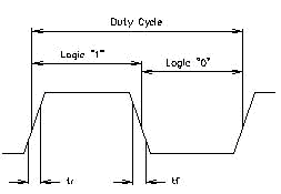
Square wave Waveform
Logic - The vast majority of systems require a crystal
oscillator output that is TTL compatible, CMOS compatible, ECL compatible or
some combinations of logic families such as TTL/HCMOS compatible.
Details on those output logic are summarized in the following tables:TTL (Transistor – Transistor Logic)
|
Logic Levels: 1:
|
2.4 V MIN
|
|
2:
|
0.4 V MAX
|
|
Duty Cycle:
|
Measured at 1.4 V
|
|
Typical Fan-out:
|
10 Loads (Gates)
|
|
Types of TTL:
|
S, LS, FAST. AS
|
|