|
(1)
Connect the resistance (R) to the circuit in series with the quartz crystal
(2) Adjust R so that oscillation can start (or stop)
(3) Measure R when oscillation just start (or stop )in above(2)
(4) Get the negative resistance -R=R+R1
(5) recommended I-RI I-RI>Re*(5 to 10)
Characteristics of Frequency vs.Load Capacitance
For many applications there are requirements to pull crystal
frequency by using a load relative element. This may be necessary
in order to trim out the manufacturing tolerance or phase
locked loop and frequency modulation applications.
In most applications the load reactive element in capacitive
and therefore only this case is now considered(Fig.9.)
The fractional
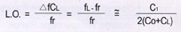 difference
in frequency between the load resonance frequency (FL) and
the resonance frequency (Fr) is known as the load resonance
frequency offset(L.O.).
In many applications a variable capacitor (trimmer)is used as
the load reactive element to adjust the frequency. The fractional
frequency range available between specified values of this load
reactive
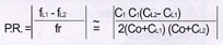 element
is called the pulling(P.R.) and it can be calculated by using
the following formula: element
is called the pulling(P.R.) and it can be calculated by using
the following formula:A useful parameter to
the design engineer is the pulling sensitivity(S) at a specified
value of load capacitance.
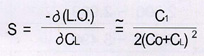 It
is defined as the incremental fractional frequency change for
an incremental change in the load capacitance. It is normally
expressed in 10-6/pF and can be calculated from the formula: It
is defined as the incremental fractional frequency change for
an incremental change in the load capacitance. It is normally
expressed in 10-6/pF and can be calculated from the formula:
The equivalent circuit of the crystal has one other important
parameter :this is R1 the motional resistance. This parameter
controls the Q of the crystal unit and will define the level
of oscillation in any maintaining circuit. The load resonance
resistance for a given crystal unit depends upon the load capacitance
with which that unit is intended to operate the crystal manufacturer
has equipment to measure there quantities. The frequency of
oscillation is the same in either a series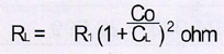 or parallel connection of the load capacitance. If the external
capacitance is designed the load resonance resistance (R1)
may be calculated as follows:
or parallel connection of the load capacitance. If the external
capacitance is designed the load resonance resistance (R1)
may be calculated as follows:
|