Equivalent Circuit
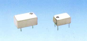
A quartz crystal resonator is
a mechanically vibrating system that is linked, via the piezoelectric effect, to
the electrical world. It
consists of a quartz plate with metal plating (electrodes), which is located on
both sides of the quartz plate and is connected to insulated leads on the
crystal package. Although the
theoretical analysis of this device is a relatively complex electro-mechanical
function, it can be expressed in terms of a simple equivalent circuit in the
vicinity of the resonance frequencies as shown below:
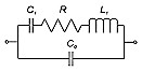
Equivalent electric circuit of quartz crystal resonator
The C0, called the “shunt” or static
capacitance, is the capacitance due to the electrodes on the crystal plate plus the
stray capacitances due to the crystal enclosure.
Shunt capacitance is present whether the crystal plate is oscillating or
not (unrelated to the piezoelectric effect of the quartz).
The R, C1 and L1 portion of the circuit is known as
the “motional arm”, which arises from the mechanical vibrations of the crystal.
R represents the equivalent motional arm resistance; C1 represents the motional capacitance of the
quartz; and L1 is the motional inductance, a function of the mass.
The C0 to C1 ratio is a measure of the interconversion between electrical
and mechanical energy stored in the crystal, i.e., of the piezoelectric coupling
factor, k. C0/C1
increases with the square of the overtone number.
When a dc voltage is applied to the electrodes of a resonator, the
capacitance ratio C0/C1 is also a
measure of the ratio of electrical energy stored in the capacitor formed by the
electrodes to the energy stored elastically in the crystal due to the lattice
strains produced by the piezoelectric effect.
When working with most
crystal resonators, it is only necessary to specify one motional
component or the other due to the absolute correlation between C1 and
L1 (C1*L1 is constant for a given series
resonant frequency). The industry
standard is to specify a proper value of C1 only.
The actual value of C1 has physical limitations when it is
realized in a quartz crystal design. These
constraints include the quartz cut, the mechanical design, the mode of operation
and the nominal frequency of the crystal resonator.
Although the equivalent circuit appears relatively simple, determining the
several characteristic frequencies useful in describing resonator equivalent
circuit properties is surprisingly complex.
For the most part, simple approximations are used.
The following notation is useful in determining some of these
frequencies.
Fs (Series resonance frequency) = 1 / [2p(L1C1)1/2]
Fp (Parallel Resonance frequency) = fs[1 + 1/(2g)]
g
(Capacitance ratio) = 2pfsC0
/ C1
Q (Quality factor) = 2pfsL1
/ R1
M (Figure of merit) = Q / g
Series vs. Parallel Resonance
The frequency at which oscillation occurs defined by fs is called
Series Resonance Frequency. The
reactance/impedance curve of a crystal shown below reveals where mechanical
resonance occurs.
Series resonance occurs at the point the curve crosses zero.
At this point, the crystal appears resistive in the circuit, impedance is
at minimum and current flow is at maximum.
As the frequency is increased beyond the point of series resonance, the
crystal appears inductive in the circuit. When
the reactance of the motional inductance and shunt capacitance cancel, the
crystal is at the frequency called Anti-resonance Frequency denoted as (fp).
At this point, impedance is maximized and the current flow is minimized.
The frequency of a crystal at fp is inherently unstable and
should be never selected as the frequency of operation for an oscillator.
The region between fs and fp is typically called “Area of Parallel
Resonance”. Parallel resonance
can occur by adding load capacitance to the crystal in series resulting a
positive frequency shift determined by:
Df
= fsC1/2(C0 + CL)
The unavoidable presence of Co in the equivalent circuit produces
this anti-resonance, sometimes also called parallel resonance.
In this connection, r = C0/C1 is an important
resonator parameter because it is inversely proportional to the spacing between
resonance and antiresonance and thereby determines the maximum bandwidth in
filters and the tuning range in oscillators.
|